

 English
 日本語
日本語 Deutsch
 عربى
عربى 中文
中文
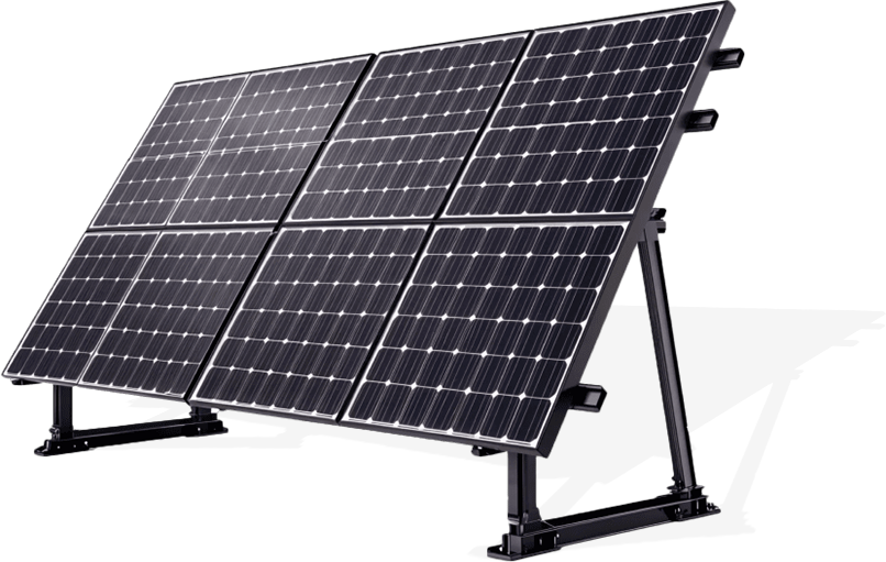
十六年にわたる太陽光架台の製造実績 
製品情報 
会社ビデオ


標準生産ライン

年間生産能力

特許数

技術スタッフ
 技術サポート
柔軟かつ迅速な技術対応により、構造計算書・シミュレーション解析・現地試験などを的確にご提供。スムーズなプロジェクト進行をサポートします。
 サービス対応
設計から施工完了まで、技術・商務の両面でトータルサポート。アフターサービス体制も整っており、安心してお任せいただけます。
 開発チーム
開発チーム
50名以上の専門開発チームと、約100件の特許を保有。お客様のニーズに応じたカスタマイズ設計にも柔軟に対応可能です。
 認証
認証
品質マネジメントシステム認証および3A企業信用等級の取得により、製品の信頼性と企業の信用力を証明しています。
 品質保証
品質保証
品質管理プロセスに基づき、高品質な製品を安定供給。お客様に安心と信頼をお届けします。
 生産体制
生産体制
5S管理手法を導入し、年産能力3万トンを実現。設計・製造・施工の豊富な経験を活かし、スピーディーかつ高品質な納品を可能にしています。


 2026/07/23
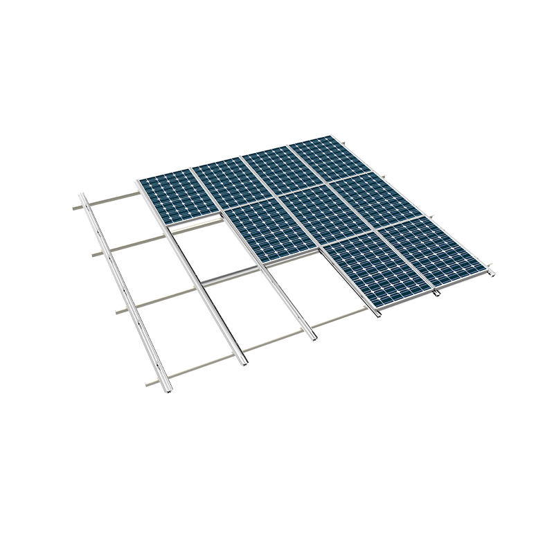
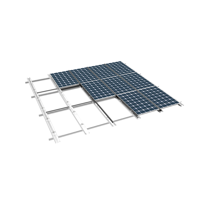
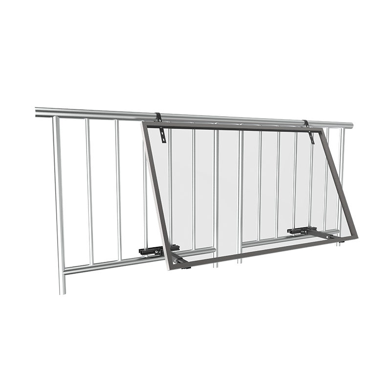
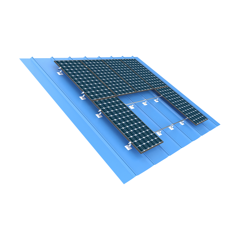
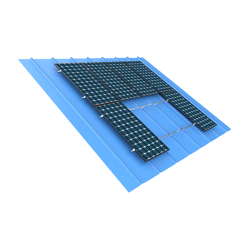
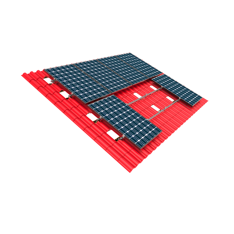
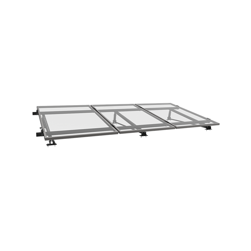
傾斜屋根 PV マウント システム: 包括的なエンジニアリングおよび選択ガイド 傾斜屋根の PV 設置システムの選択は、屋上太陽光発電設置において最も重要なエンジニアリング上の決定であり、構造の完全性、耐候性、長期的なエネルギー生産に直接影響します。 最新のシステムは大幅に進化しており、レールレス ソリューションでは、材料コストと設置時間を削減しながら、従来のレール付きシステムと同等の強度を提供できるようになりました。価値の高い商業施設や住宅施設の場合、システムが 25 年以上の極端な気象条件に耐えられるように、アルミニウムとステンレス鋼のコンポーネントの選択、水切りと防水の詳細設計、および風による浮き上がり抵抗の計算を注意深く評価する必要があります。 傾斜屋根 PV マウント システムを理解する: コア コンポーネントと機能 A 傾斜屋根用太陽光発電設置システム 太陽電池パネルを屋根構造に確実に機械的に取り付けることと、水の浸入に対して屋根外皮の完全性を維持することという 2 つの重要な機能を実行します。通常、システムは次の 4 つの主要なコンポーネント カテゴリで構成されます。 屋根の付属品: 屋根垂木またはトラスに固定された屋根フック、ブラケット、またはレール。これらは、PV アレイから建物の構造に重量と風荷重を伝達します。 取り付けレール: 屋根表面と平行に走る水平レール (またはレールのない構造セクション) は、パネルを支え、傾斜を最適化するために高さ調整を行います。 パネルクランプ: 熱による膨張と収縮を許容しながら、各 PV パネルをレール システムに固定する中間クランプとエンド クランプ。 フラッシングとシーリング: 屋根の貫通部からの水の侵入を防ぐ防水水切りとシーリングコンポーネント。これはおそらく建物保護の観点から最も重要な要素です。 傾斜屋根 PV マウント システム: レール付き、レールレス、統合型ソリューション 次の表では、3 つの主要な機能を比較しています。 傾斜屋根用太陽光発電設置システム 現在太陽光発電市場で入手可能な構成。 パラメータ 従来のレールシステム レールレスシステム ビル内統合型(BIPV) 構造原理 アタッチメント間をまたぐ全長レール 個々の取り付けポイントに直接取り付けられたクランプ 従来の屋根材に代わるパネル マテリアルコンテンツ 高(レール、クランプ、アタッチメント) 低 (クランプのみ、ロングレールなし) 最高(素材の二重機能) インストール速度 中程度 (段階的なプロセス) 高速 (レールよりも最大 30 ~ 40% 高速) 遅い (屋根の統合が必要) システム重量 (kg/m²) 5-8 3-5 12-18 耐風上げ抵抗 優れた (連続レールサポート) 良好 (点荷重分散) 優れた(アタッチメント一体型) モジュールの互換性 ユニバーサル ユニバーサル with adapter clamps 独自仕様(パネル固有) 相対コスト 中程度 (0.30 ~ 0.45 ドル/W) 低 ($0.20-0.35/W) 高 ($1.00-1.50/W) 材料の選択: 傾斜屋根 PV 設置システムにおけるアルミニウムとステンレス鋼 材料の選択 傾斜屋根用太陽光発電設置システム 耐食性、強度、重量、コストに大きな影響を与えます。 アルミニウム (6000 シリーズ): レール、クランプ、構造コンポーネントに最も一般的な材料。優れた強度重量比、製造の容易さ、自然酸化物の形成による良好な耐食性を実現します。アルミニウム製コンポーネント 傾斜屋根用太陽光発電設置システム 通常、同等の鋼材よりも 40 ~ 60% 軽く、屋根にかかる構造負荷が軽減されます。ただし、アルミニウムは異種金属と接触すると電気腐食を受ける可能性があるため、締結具や絶縁ワッシャーを慎重に選択する必要があります。 ステンレス鋼 (304/316): 主に屋根の取り付け、留め具、高負荷の接続に使用されます。特に沿岸環境や酸性雨が降る地域で優れた耐食性を発揮します。ステンレス鋼のコンポーネントは優れた耐久性を備えていますが、アルミニウムに比べてコストが 2 ~ 3 倍高く、非常に重いです。 亜鉛メッキ鋼: 特に中層市場において、屋根アタッチメントの費用対効果の高い代替品です。溶融亜鉛めっきコンポーネントは 15 ~ 20 年間優れた腐食保護を提供しますが、過酷な環境では検査とタッチアップが必要になる場合があります。 ほとんどの住宅および商業用途では、全アルミニウム製 傾斜屋根用太陽光発電設置システム ステンレススチール製の留め具を使用すると、性能、重量、コストの最適なバランスが得られます。海水から 5 km 以内の沿岸に設置する場合は、隙間腐食を防ぐために 316 グレードのステンレス鋼の屋根アタッチメントにアップグレードすることを強くお勧めします。 風荷重工学 傾斜屋根の太陽光発電システムの風による揚力は、強風地域では 2.5 kN/m² を超えることがあります。適切なアンカー間隔 (通常 1.2 ~ 1.8 m) と耐風性を考慮して設計されたレール プロファイルにより、極端な条件下でもシステムの安全性が確保されます。 熱の動き 太陽光発電パネルは、温度変化により 1 メートルあたり最大 3 mm 伸縮します。クランプは、パネル フレームやガラスにストレスを与えることなく、熱膨張に対応する必要があります。エラストマークランプとスロット付きレールチャネルは、この目的のために設計されています。 防火規制への準拠 ほとんどの建築基準法では、PV アレイの下にクラス A 耐火屋根カバーを設置する必要があります。取り付けシステムは、火や残り火の蓄積を管理するために十分なクリアランス (50 ~ 100mm) を提供する必要があります。 傾斜屋根 PV 設置システムの風荷重の計算 風による揚力は、あらゆるものにとって最も重要な荷重ケースです。 傾斜屋根用太陽光発電設置システム 。 ASCE 7-16 およびユーロコード 1 は、建物に取り付けられた太陽電池アレイの風荷重を計算するための標準化された方法論を提供します。 風荷重計算における主な要素は次のとおりです。 建物の高さと露出のカテゴリ: 高い建物や開けた地形の敷地では、より高い風速が発生します。露出 C (開けた地形) の高さ 10 メートルの建物は、露出 B (郊外の地形) の同じ建物よりも 20 ~ 30% 高い風圧を受ける可能性があります。 屋根のピッチ: 屋根の傾斜は風圧の分布に影響します。最も高い上昇圧力は通常、屋根の端と尾根から 1.0 ~ 1.5 メートル以内で発生します。 パネル配列サイズ: アレイが大きくなると、アレイの先端での隆起が増加します。構造エンジニアは、設計時にエッジと内部ゾーンの圧力を考慮する必要があります。 傾斜屋根用太陽光発電設置システム . 安全率: 業界の慣例では、システムの耐用年数にわたる風圧分布と材料の挙動の不確実性を考慮して、計算された風荷重に 1.5 ~ 2.0 の安全率が適用されます。 屋根の取り付け方法:技術の比較 具体的な取り付け方法は、 傾斜屋根用太陽光発電設置システム 屋根の構造への影響は、屋根の構造のタイプ(木製垂木、鋼製母屋、またはコンクリートタイル)によって異なります。 垂木へのラグボルト (木造屋根): 木造屋根の最も一般的な工法です。ルーフフックは、50〜100mmの埋め込みを持つラグボルトを使用して垂木に固定されます。この方法は優れた荷重伝達を実現しますが、垂木の正確な位置が必要であり、垂木の間隔が 600mm を超える場合には適していません。 スタンディングシームルーフクランプ: 金属製の立ち継ぎ目屋根の場合、特殊なクランプが屋根を貫通することなく継ぎ目に取り付けられます。これにより屋根の保証が維持され、雨漏りのリスクが排除されます。 傾斜屋根 PV 架台システム 立ち継ぎ屋根の設計は、最も早く設置できるものの 1 つです。 コンクリートタイルフック: 粘土およびコンクリートのタイル屋根には、個々のタイルを交換して、下にある当て木に取り付けるタイルフックが必要です。これらのフックは、構造フレームに荷重を分散しながら屋根の外観を維持します。 接着剤およびバラストシステム: 特定の地域では接着剤ベースの使用が許可されています 傾斜屋根用太陽光発電設置システム 屋根貫通部のないアタッチメント。これらのシステムは、耐用年数 25 年と評価された構造用接着剤に依存しており、通常はポリウレタンまたはシリコーンベースの配合物が使用されます。 防水の完全性: 傾斜屋根 PV 架台システムの重要な詳細 A 傾斜屋根用太陽光発電設置システム 雨漏りは建物に大きな損害を与える可能性があります。屋根貫通防水戦略はおそらく、品質に関する最も重要な考慮事項です。 防水に関するベスト プラクティスは次のとおりです。 ステップ点滅: 瓦屋根の場合、瓦コースと一体化したステップ水切りにより貫通部の周囲の水の流れが確保されます。各水切り部分が下の部分と重なり、防水シールが形成されます。 EPDM または TPO ブーツ: こけら屋根の場合、裏面に粘着剤が付いた EPDM ブーツが屋根フックの周囲に耐候性のシールを作成します。これらのブーツはほとんどの屋根膜システムと互換性があり、20 ~ 30 年の耐用年数を提供します。 シーラントの塗布: 高品質のポリウレタンまたはシリコーンシーラントがすべての貫通ポイントに適用されます。シーラントは屋根材および取り付けシステムのコンポーネントと適合する必要があります。 ストレスリリーフ設計: の 傾斜屋根用太陽光発電設置システム 防水に負担をかけずに熱の動きに対応するために、貫通点に応力緩和ループまたは柔軟なブッシュを組み込む必要があります。 評判の良い 傾斜屋根用太陽光発電設置システム メーカーは、事前に組み立てられた単一のコンポーネントに取り付け機能と防水機能を組み合わせた統合型水切りソリューションを提供しており、設置を簡素化し、漏れのリスクを軽減します。 不動産所有者にとって重要な洞察: の typical cost of repairing a roof leak caused by an improperly installed pitched roof PV mounting system is $1,500-$5,000. Investing in a premium flashing system and qualified installation is far less costly than addressing water damage to insulation, ceilings, and structural framing. 設置効率: システム設計が人件費に与える影響 のデザイン 傾斜屋根用太陽光発電設置システム これは設置に必要な労働力に直接影響を及ぼし、これはシステム総コストの 30 ~ 50% を占める可能性があります。 組み立て済みのレールシステム: 一部のメーカーは、現場での切断や穴あけを軽減する事前に組み立てられたレールセクションを提供しています。これら 傾斜屋根用太陽光発電設置システム この設計により、設置時間を 15 ~ 20% 短縮できます。 レールレス システム: レールレス設計では、個々のパネル クランプをルーフ フックに取り付けるだけで済み、レールの取り付け手順が完全に不要になります。レールレス化により、設置時間を 30 ~ 40% 短縮できます。 傾斜屋根用太陽光発電設置システム 大規模な住宅開発で人気が高まっているデザイン。 モジュール式コンポーネント: 標準化されたコンポーネントとシンプルな組み立て手順を備えたシステムにより、設置チームの学習曲線が短縮され、組み立てエラーのリスクが最小限に抑えられます。 大量の商用設置の場合、パネルごとの設置時間を 5 分でも短縮するだけで、大規模なプロジェクト全体で大幅な労力の節約につながる可能性があります。これは、製品を選択する際の重要な考慮事項です。 傾斜屋根用太陽光発電設置システム . 傾斜屋根太陽光発電設置システムのコンプライアンスと認証 A 傾斜屋根用太陽光発電設置システム 適用される建築基準法および業界標準に準拠する必要があります。主なコンプライアンス要件は次のとおりです。 ASCE 7-16 (風荷重): すべてのシステムは、設置場所に指定された設計風速に耐えるように設計する必要があります。構造エンジニアは、風による揚力についてシステムを認証する必要があります。 IBC と IRC: の International Building Code and International Residential Code provide prescriptive requirements for rooftop solar installations, including structural load calculations, fire safety clearances, and accessibility requirements. UL 2703: この規格は、取り付けシステム、接地、および接着要件を含む、ソーラー パネルの取り付けシステムを対象としています。 UL認定済み 傾斜屋根用太陽光発電設置システム コンポーネントは構造的完全性と耐火性についてテストされています。 製品認証: TÜV、CE、および CSA 認定は、 傾斜屋根用太陽光発電設置システム メーカーの製品の品質と性能に関する主張。 を指定する場合 傾斜屋根用太陽光発電設置システム 、これらの規格に準拠していることを示す文書化された証拠が必要です。準拠していないシステムは建築検査官によって拒否される可能性があり、その結果、プロジェクトの遅延に費用がかかります。 接地と接着: 傾斜屋根の PV 設置システムの電気的安全性 A 傾斜屋根用太陽光発電設置システム 太陽電池アレイの接地経路として機能します。米国電気工事法 (NEC) 第 690 条では、太陽光発電システムのすべての金属コンポーネントが適切に接着され、接地されることを要求しています。 統合されたボンディング: 現代の多くの 傾斜屋根用太陽光発電設置システム 設計には接着ワッシャーまたはクリップが組み込まれており、すべてのアルミニウムコンポーネントが電気的に連続していることを保証します。これにより、別途ボンディング ジャンパーを使用する必要がなくなり、設置時間と材料コストが削減されます。 接地電極接続: の 傾斜屋根用太陽光発電設置システム 通常は 6 AWG 銅導体を介して、建物の接地電極システムに接続する必要があります。接続ポイントは、検査およびテストのためにアクセスできる必要があります。 異種金属: アルミニウムと銅の間のガルバニック腐食には、バイメタル コネクタまたは錫メッキ銅接合コンポーネントを使用して対処する必要があります。 適切な接地は、電気の安全性だけでなく、落雷保護や機器の保証準拠のためにも不可欠です。 傾斜屋根太陽光発電設置システムのライフサイクルコスト分析 の初期費用 傾斜屋根用太陽光発電設置システム ライフサイクルコスト全体の一部にすぎません。価値の高い顧客の場合は、コスト分析に次の要素を含める必要があります。 材料費: システムのタイプ (レールレス、レール付き、または一体型) に応じて、1 ワットあたり 0.20 ドルから 0.50 ドル。 10 kW システムの場合、材料費は 2,000 ドルから 5,000 ドルの範囲です。 取り付け作業: 1 ワットあたり 0.15 ~ 0.30 ドル。システムが高速化すると、人件費が削減され、プロジェクトのスケジュールが短縮されます。 メンテナンス費用: 年に一度の検査と締め具の締め付けが必要な場合があります。プレミアム システムの場合、メンテナンス コストは最小限で、通常は中規模のアレイで年間 200 ドル未満です。 交換費用: の 傾斜屋根用太陽光発電設置システム 屋根自体は交換が必要になることはほとんどありませんが、屋根を葺き替える際に屋根下地材にアクセスして交換するコストを考慮する必要があります。残り耐用年数が 15 年未満の屋根にシステムを設置する場合、これは重大な問題となります。 包括的なライフサイクルコスト分析により、保険料に 15 ~ 20% 多く投資する必要があることが判明する可能性があります。 傾斜屋根用太陽光発電設置システム 優れた腐食保護と迅速な設置により、25 年間にわたる総コストを削減します。 傾斜屋根太陽光発電設置システムに関するよくある質問 レールレス傾斜屋根太陽光発電設置システムとレール付き傾斜屋根太陽光発電設置システムの違いは何ですか? レール システムでは、屋根アタッチメント間にまたがる連続レールを使用してパネルをサポートします。レールレスシステムは、個々のクランプを介して各パネルをルーフフックに直接取り付けます。通常、レールレス システムは設置が早く、使用する材料も少なくなりますが、レール付きシステムは継続的に荷重が分散されるため、風による浮き上がりに対する抵抗力が高くなります。 私の屋根構造が傾斜屋根の PV 設置システムをサポートできるかどうかを確認するにはどうすればよいですか? 構造エンジニアは既存の屋根構造を評価する必要があります。評価には、垂木の間隔、サイズ、状態のチェック、追加の死荷重 (通常、取り付けシステムとパネルの場合 12 ~ 18 kg/m²) および風による揚力荷重の計算が含まれます。ほとんどの住宅の屋根は太陽電池アレイをサポートできますが、古い屋根や損傷した屋根には補強が必要な場合があります。 傾斜屋根の PV 設置システムでの漏れを防ぐために、屋根の貫通部はどのように密閉されていますか? 屋根の貫通部は、統合された水切りシステム、EPDM ブーツ、または耐候性シール付きのタイルフックを使用してシールされます。通常、水切り、シーラント、場合によっては二次膜など、複数の重複する保護層が使用されます。プレミアム システム メーカーは、事前に設計された防水の詳細を備えた屋根固有の取り付けソリューションを提供しています。 傾斜屋根の PV 設置システムではどのような認定を探す必要がありますか? UL 2703 リスト (米国) または CE マーキング (EU)、TÜV 認証、ASCE 7 (風荷重) および現地の建築基準への準拠を探してください。一部のメーカーは、耐風揚力および腐食性能に関する認定研究所からの製品固有の試験レポートも提供しています。 傾斜屋根の PV 設置システムは通常どのくらいの期間使用できますか? 高品質の傾斜屋根 PV マウント システムは、ソーラー パネルの通常の保証期間と一致する 25 年の耐用年数を想定して設計されています。適切な陽極酸化処理または粉体塗装を施したアルミニウム コンポーネントとステンレス鋼製ファスナーを組み合わせると、ほとんどの環境で 30 年を超える耐用年数を実現できます。耐食合金は海岸や工業地帯には不可欠です。 .solar-article { max-width: 1520px; margin: 0 auto; } .solar-article * { box-sizing: border-box; } .solar-article p, .solar-article li, .solar-article td { font-size: 17px; line-height: 30px; color: #1e1e1e; } .solar-article h2 { font-size: 28px; font-weight: 700; color: #2a4a1a; margin-top: 48px; margin-bottom: 18px; letter-spacing: -0.01em; border-bottom: 3px solid #6cb851; padding-bottom: 10px; display: inline-block; } .solar-article h3 { font-size: 22px; font-weight: 600; color: #3a8a2a; margin-top: 32px; margin-bottom: 12px; } .solar-article h4 { font-size: 18px; font-weight: 600; color: #2a4a1a; margin-top: 24px; margin-bottom: 6px; } .solar-article p { margin-bottom: 22px; } .solar-article ul, .solar-article ol { padding-left: 26px; margin-bottom: 26px; } .solar-article li { margin-bottom: 10px; } .solar-article strong { color: #3a8a2a; font-weight: 600; } .lead-answer { background: #eef8ea; border-left: 6px solid #6cb851; padding: 20px 28px; border-radius: 0 12px 12px 0; margin-bottom: 30px; font-size: 19px; line-height: 34px; } .solar-table { width: 100%; border-collapse: collapse; margin: 28px 0 36px; border-radius: 14px; overflow: hidden; box-shadow: 0 4px 18px rgba(108, 184, 81, 0.10); font-size: 16px; line-height: 28px; } .solar-table tr { border-bottom: 1px solid #d4e8ca; } .solar-table tr:last-child { border-bottom: none; } .solar-table tr:nth-child(even) { background-color: #f2faf0; } .solar-table tr:first-child { background-color: #6cb851; color: white; font-weight: 600; } .solar-table td { padding: 14px 18px; vertical-align: top; } .solar-table tr:first-child td { font-weight: 600; letter-spacing: 0.3px; } .feature-grid { display: grid; grid-template-columns: repeat(auto-fit, minmax(240px, 1fr)); gap: 20px; margin: 28px 0 32px; } .feature-card { background: #f2faf0; border: 1px solid #d4e8ca; border-radius: 16px; padding: 22px 20px; transition: 0.2s ease; } .feature-card:hover { border-color: #6cb851; box-shadow: 0 6px 20px rgba(108, 184, 81, 0.08); } .feature-card h4 { color: #6cb851; font-size: 18px; margin: 0 0 6px 0; } .feature-card p { font-size: 16px; line-height: 28px; margin: 0; } .highlight-box { background: #2a4a1a; color: #ffffff; border-radius: 14px; padding: 22px 30px; margin: 30px 0; } .highlight-box p { color: #eaf8e5; margin-bottom: 0; } .highlight-box strong { color: #8fd67a; } .faq-block { margin-top: 48px; border-top: 3px solid #d4e8ca; padding-top: 28px; } .faq-item { border-bottom: 1px solid #d4e8ca; padding: 18px 0; } .faq-item:last-child { border-bottom: none; } .faq-q { font-weight: 700; font-size: 18px; color: #2a4a1a; display: flex; gap: 10px; } .faq-q::before { content: "Q"; color: #6cb851; font-weight: 800; } .faq-a { padding-left: 32px; font-size: 17px; line-height: 30px; margin-top: 2px; } .faq-a::before { content: "A"; color: #6cb851; font-weight: 700; margin-right: 10px; } @media (max-width: 640px) { .solar-article { padding: 0 4px; } .solar-table td { display: block; width: 100%; padding: 12px 16px; border-bottom: none; } .solar-table tr { display: block; margin-bottom: 18px; border: 1px solid #d4e8ca; border-radius: 12px; } .solar-table tr:first-child { display: none; } .feature-grid { grid-template-columns: 1fr; } .lead-answer { padding: 16px 18px; font-size: 17px; line-height: 30px; } .faq-a { padding-left: 0; } }
2026/07/23
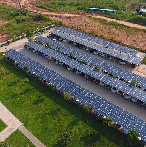
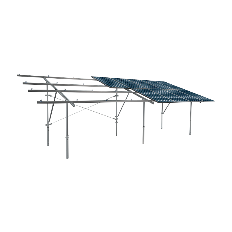
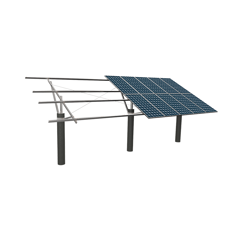
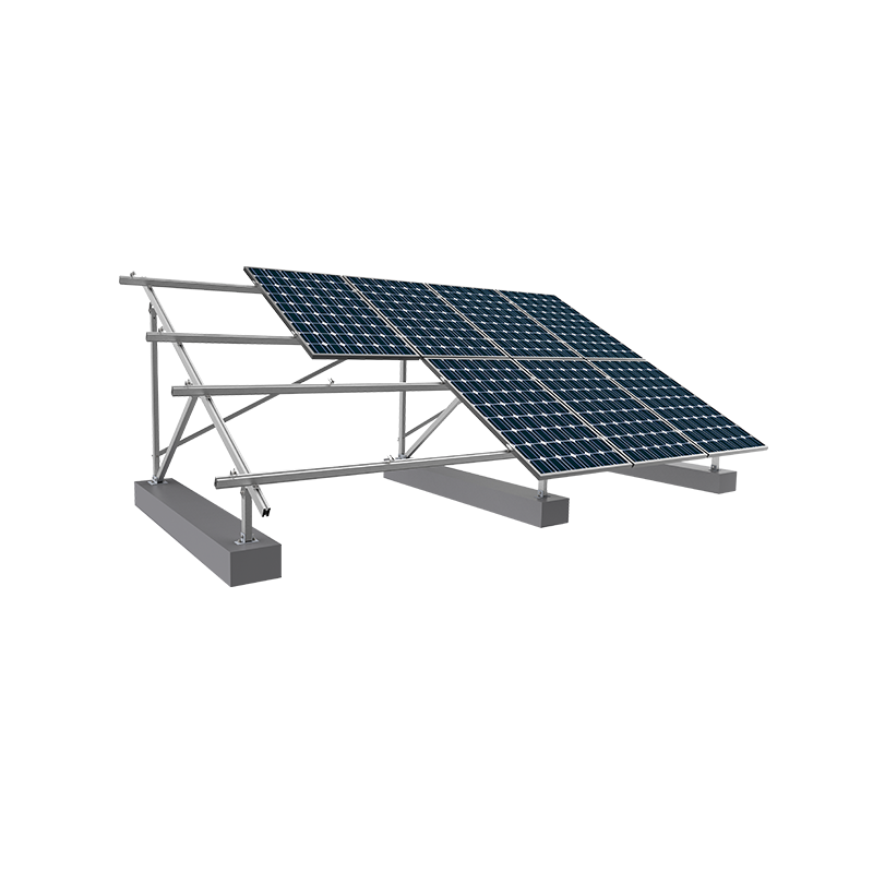
2026/07/16商用グレードの実装 カーポート PV マウント システム は、空きアスファルト不動産を大容量エネルギー生成プラットフォームに変換したいと考えている資産管理者に、即時かつ高利回りのソリューションを提供します。築年数、屋根の保証、複雑な構造荷重制限によって制限される従来の屋上設置とは異なり、地上設置型ソーラーカーポートは、クリアスパンエンジニアリングを利用して車両を保護しながら、予測可能なクリーンパワーを生成します。エンタープライズレベルの物流ハブ、企業キャンパス、小売開発業者にとって、構造ラックアーキテクチャの選択は、長期的な ROI、局所的な風荷重耐性、および 25 年の運用ライフサイクルにわたる資産の耐久性を決定する最も重要な要素です。 バックボーンのエンジニアリング: 構造用炭素鋼と陽極酸化アルミニウム合金 の構造的基礎 カーポート PV マウント システム 継続的な環境ストレス、動的風荷重、および潜在的な車両衝撃にさらされています。正しい主合金を選択すると、支柱間のスパン、構造基礎の深さ、および長期メンテナンスのオーバーヘッドが決まります。 溶融亜鉛めっき炭素鋼(Q235B・Q355B) 構造用鋼は、柱の間隔が 6 ~ 9 メートルを超える必要がある長スパンの複数車両の商業施設のゴールドスタンダードであり続けています。 構造降伏強度: 優れた耐荷重により、広いクリアランス高さが可能になり、重量があり高ワットの両面受光ガラスオンガラス太陽電池モジュールのサポートが可能になります。 スパンの最適化: メガワットあたりに必要な基礎の総数が減り、土木掘削コストが削減されます。 腐食の軽減: 湿気の多い気候や沿岸地域での環境悪化を防ぐために、少なくとも 65 ~ 85 ミクロンの溶融亜鉛めっきの厚さが必要です。 高強度アルミニウム合金押出材(AL6005-T5) 陽極酸化アルミニウムの構成は、美しさと組み立てのスピードが優先される中規模の企業の駐車場構造や建築設備に非常に好まれています。 デッドウェイトの軽減: 材料密度が低いため、高い構造コンポーネントにかかる重力負荷が軽減され、組み立て時の取り扱いが簡素化されます。 固有の酸化耐性: 陽極酸化皮膜は、亜鉛を豊富に含むペイントの定期的なタッチアップを必要とせずに、環境摩耗に対して強力な保護を提供します。 組み立て済みコンポーネントの手すり: 重量構造用鋼の溶接と比較して現場での労働時間を最大 35% 短縮するクリックイン クランプ システムを備えています。 技術比較マトリックス: アーキテクチャと基礎構造システム ソーラーパーキングの構成が異なると、地域の気象パターン、地震条件、レイアウト制限に応じて独自の設計許容差が必要になります。以下の表は、大容量駐車場設備に適用される 3 つの主要なエンジニアリング手法を対比させたものです。 設計仕様書 シングルポストカンチレバー デュアルポスト「W」フレーム ロングスパントラスガントリー 一次スペース効率 最大(最も簡単な車両ドアクリアランス) 中 (正確な駐車ラインが必要) 高密度の物流トラックに最適化 風雪耐荷重 最大 45 m/s (堅牢な基礎が必要) 最大60m/s(高安定分布) 優れた (走行車線全体にまたがる) 防水建築 ゴム製 EPDM 雨樋または構造用雨樋 インターロック式アルミニウム水ガイドレール 標準金属デッキ下敷きオプション 相対的な設置コスト 高 (鋼ゲージ要件の増加) ベースライン標準 (コスト効率の高い材料の使用) プレミアム (カスタムエンジニアリングオーバーヘッド) 理想的な商業的背景 高級小売店および役員用駐車場 標準的な車両倉庫と長期輸送 重量貨物ターミナルと広い走行車線 防水とシールド: 構造ラックとサブフレーム 高額資産の所有者は、商用カーポートが雨、雪、紫外線による駐車車両の磨耗を防ぐ本物の保護カバーとして機能することを期待しています。標準的な地上設置型ソーラーラッキングでは、水がモジュールの隙間を通過することができます。ただし、産業用カーポートの PV 設置システムには、専用の水管理戦略を組み込む必要があります。 エンジニアリングのベストプラクティス: 一体型の EPDM ゴム製ガスケットを備えた構造的にかみ合うアルミニウム レール プロファイルを組み込むことで、モジュールの継ぎ目で雨水を直接捕らえます。これにより、厚い波板金属の下敷きを追加することなく、流れを周囲の縦樋に導きます。下部の金属デッキを廃止することで、材料コストがワットあたり最大 0.12 ドル削減され、同時に両面受光型 PV パネルの背面の通気性が向上します。 動作温度は太陽電池モジュールの性能に大きく影響します。従来のアンダーデッキ構成では、熱気が PV アレイの直下に蓄積し、動作温度が 65°C を超えて急上昇します。これにより、モジュールの温度係数に基づいて熱出力の低下が引き起こされ、有効エネルギー出力が 8% ~ 12% 減少します。オープンレールのマイクロガター取り付け設計を利用することで、自然の風の流れでモジュールを下から冷却し、暑い夏の期間でもピークの発電効率を維持できます。 基礎工学と土木コストの最適化 土木工事、コンクリートの注入、掘削は、ソーラー カーポート プロジェクトの総資本支出の 30% ~ 40% をすぐに占めることがあります。適切な基礎システムの選択は、駐車場の土壌の組成と局所的な風による隆起の計算によって決まります。 現場打ちボーリングコンクリート橋脚: 変わりやすい土壌や強風の環境に最も信頼できるオプションです。重い鉄筋コンクリートの橋脚が地表から 2 ~ 4 メートル下まで伸びており、高いカンチレバーの設計にかかるてこの力に対抗します。 プレキャストコンクリートバラストブロック: 地下電線や自治体の環境保護のため掘削が制限されている場合に使用されます。これらのシステムは、ラッキングの安定性を維持するために純粋に重い質量に依存していますが、広い設置面積が必要であり、場合によっては利用可能な駐車スペースが減少する可能性があります。 駆動鋼製 H 杭: 深く石のない土壌プロファイルを備えた大規模な未開発のフリートパーキング構造に非常に適しています。重機が杭を地面に直接打ち込むため、コンクリートの硬化に必要な時間が不要になり、設置スケジュールが短縮されます。 財務指標と高価値資産の統合 運用コストの観点から見ると、キャノピーベースのカーポート PV 取り付けシステムを導入することで、商業不動産所有者は不安定な電気料金に対する効果的なヘッジを提供できます。太陽電池アレイとレベル 2 またはレベル 3 の DC 高速 EV 充電ステーションを組み合わせることで、高収量のマイクログリッド インフラストラクチャが構築されます。不動産管理者は、グリーン充電電力をフリート運営者やテナントに割高で直接販売できるため、回収期間が短縮されます。 たとえば、二重支柱スチール製取り付けシステムで覆われた 500 スペースの小売駐車場は、約 1.5 メガワット (MW) の太陽光発電容量をサポートできます。このシステムは高日射量地域で推定年間 2,250,000 kWh を発電し、商用料金 0.15 ドル/kWh で光熱費を最大 337,500 ドル相殺できます。現地の加速償却規則や連邦投資税額控除と組み合わせると、このインフラ投資は通常 5 ~ 7 年以内に資本の完全償却を達成し、20 年以上の低維持キャッシュ フローが残ります。 よくある質問 市販のカーポート PV 取り付けシステムの一般的な傾斜角度はどれくらいですか? 商用ソーラーカーポートは通常、5〜15度の低い傾斜角で設計されています。この角度により、年間を通じて太陽エネルギーを吸収する必要性と低い風の抵抗のバランスが取れ、同時に適切な水の流出を確保してほこりや破片がパネルに蓄積するのを防ぎます。 ソーラーカーポートは、長い鋼鉄またはアルミニウムのレール全体の熱膨張をどのように管理しますか? 長く連続したアルミニウムまたはスチールのレールには、15 ~ 20 メートルごとに特殊な伸縮ジョイントが組み込まれています。これらの機械的ギャップにより、季節ごとの激しい温度変動時にも構造が安全に伸縮できるため、構造の歪みや太陽電池モジュールのフレームへの危険な応力が防止されます。 カーポート PV 取り付けシステムは、平坦でない駐車場や傾斜のある駐車場にも適応できますか? はい。プレミアム取り付け構成は、調整可能なコラム接続と可変伸縮式後脚を備えています。この施工公差により、エンジニアリング チームは、コストのかかるレベリングや既存のアスファルトの再整地を必要とせずに、最大 10% の傾斜に対応できます。 商用車や商用車にはどのような標準的なクリアランス高さが必要ですか? 標準的な乗用車のキャノピーは、2.5 ~ 3.0 メートルの高さで作られています。物流ヤード、配送センター、公共交通機関のバスベイでは、大型貨物トラックや緊急車両を安全に収容できるよう、地上高が 4.5 ~ 5.2 メートルに増加します。 両面受光型太陽電池モジュールの使用は、取り付けシステムの設計にどのような影響を与えますか? 両面受光型ソーラーモジュールは、駐車場の表面から反射した光を吸収することで追加のエネルギーを生成します。このアルベド効果を最適化するには、取り付けシステムは、パネルのすぐ後ろに幅広の固体母屋や幅広の固体金属デッキを使用することを避ける必要があります。これにより、モジュールの背面の影が最小限に抑えられ、総エネルギー収量が 10% ~ 20% 向上します。 .cpv-article-wrapper { max-width: 1520px; margin: 0 auto; padding: 45px 25px; background-color: #ffffff; font-family: -apple-system, BlinkMacSystemFont, "Segoe UI", Roboto, "Helvetica Neue", Arial, sans-serif; font-size: 16px; line-height: 30px; color: #2d3748; box-sizing: border-box; } .cpv-article-wrapper h2 { color: #6cb851; font-size: 26px; line-height: 34px; margin-top: 45px; margin-bottom: 20px; font-weight: 700; border-bottom: 2px dashed #e2e8f0; padding-bottom: 12px; } .cpv-article-wrapper h3 { color: #2d3748; font-size: 20px; line-height: 28px; margin-top: 10px; margin-bottom: 15px; font-weight: 600; } .cpv-article-wrapper h4 { color: #6cb851; font-size: 18px; line-height: 26px; margin: 0 0 10px 0; font-weight: 600; } .cpv-article-wrapper p { margin-top: 0; margin-bottom: 24px; color: #4a5568; } .cpv-lead-text { font-size: 18px; line-height: 32px; color: #2d3748; background-color: #f4faf2; padding: 30px; border-radius: 8px; border: 1px solid #d4edda; box-shadow: 0 2px 4px rgba(0,0,0,0.01); } .cpv-dual-column { display: flex; gap: 30px; margin: 35px 0; flex-wrap: wrap; } .cpv-column-card { flex: 1; min-width: 320px; background-color: #ffffff; border: 1px solid #e2e8f0; border-left: 5px solid #6cb851; padding: 25px; border-radius: 6px; box-shadow: 0 4px 6px rgba(0,0,0,0.02); } .cpv-article-wrapper ul { margin-top: 0; margin-bottom: 20px; padding-left: 20px; } .cpv-article-wrapper li { margin-bottom: 10px; color: #4a5568; } .cpv-table-container { width: 100%; overflow-x: auto; margin: 40px 0; border-radius: 8px; border: 1px solid #edf2f7; } .cpv-comparison-table { width: 100%; border-collapse: collapse; text-align: left; font-size: 15px; } .cpv-comparison-table th, .cpv-comparison-table td { padding: 16px 20px; border-bottom: 1px solid #edf2f7; line-height: 24px; } .cpv-comparison-table tr:first-child { background-color: #6cb851; color: #ffffff; font-weight: 600; } .cpv-comparison-table tr:nth-child(even) { background-color: #f8fafc; } .cpv-article-wrapper blockquote { background-color: #f7fafc; border-left: 4px solid #6cb851; padding: 25px; margin: 35px 0; border-radius: 4px; color: #4a5568; } .cpv-divider { border: 0; height: 1px; background: #e2e8f0; margin: 55px 0; } .cpv-faq-wrapper { margin-top: 30px; } .cpv-faq-node { background-color: #ffffff; border: 1px solid #e2e8f0; border-radius: 8px; padding: 24px; margin-bottom: 20px; box-shadow: 0 2px 4px rgba(0,0,0,0.01); } .cpv-faq-node:hover { border-color: #6cb851; box-shadow: 0 4px 12px rgba(108, 184, 81, 0.08); } @media (max-width: 768px) { .cpv-article-wrapper { padding: 25px 15px; } .cpv-dual-column { flex-direction: column; } .cpv-article-wrapper h2 { font-size: 22px; line-height: 30px; } .cpv-lead-text { font-size: 16px; line-height: 28px; padding: 20px; } }
2026/07/16
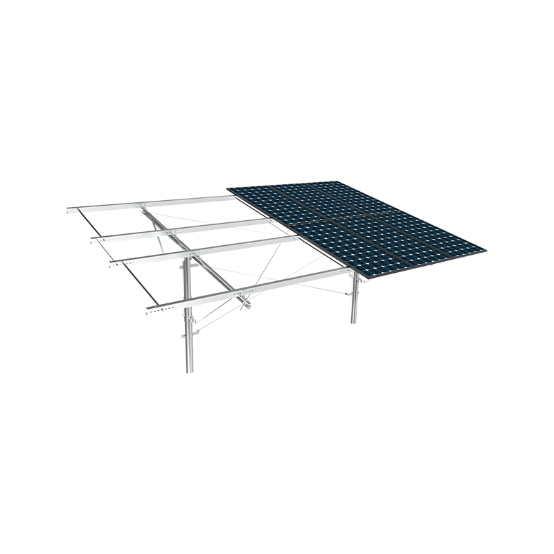
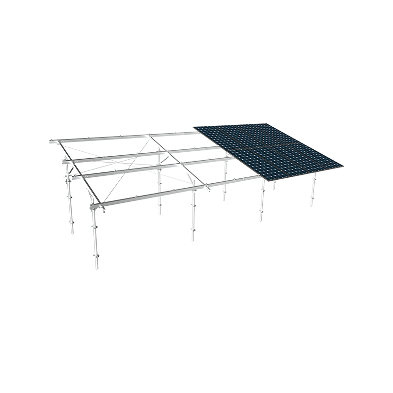
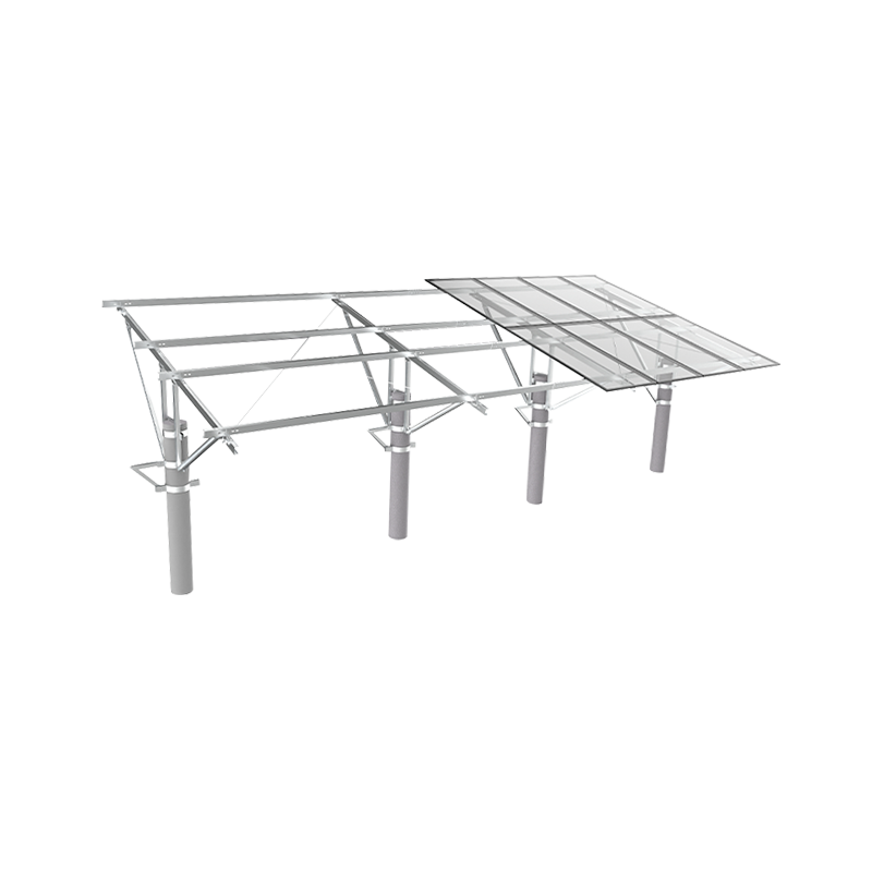
2026/07/09適切に設計された漁業と太陽光のハイブリッド太陽光発電設置システムは、池や海岸環境特有の風や水の負荷に対してしっかりと固定しながら、水生生物への太陽光の浸透を確保するのに十分な高さにパネルを持ち上げる必要があります。クリアランスの高さ、材料の耐食性、基礎のタイプを間違えると、過度の日陰による漁獲量の減少や、過小評価された水力や風力による数シーズン以内の構造破損が生じます。 3 つすべてを正しく行うかどうかが、20 年かけて投資を回収できるシステムと、5 年以内に高額な修理が必要になるシステムを分けるものです。 漁業用ソーラー設置が地上設置システムと異なる理由 標準的な地上設置型ソーラーラッキングは、開いた土地で計算された耐土性と固定風荷重を中心に設計されています。あ 漁業用太陽光発電ハイブリッド太陽光発電設置システム 水没または部分的に水没した基礎、水位の変動、継続的な湿気への曝露による腐食、そしてその下の魚や水生植物を支えるために十分な光を水面に届ける生物学的必要性など、根本的に異なる一連のストレスに直面しています。 この二重目的の要件は、パネルの傾斜角度、列間隔、および取り付け高さが、屋上や野外での場合のようにエネルギー収量を最大にすることだけを目的として選択されていないことを意味します。水面のおよそ 30 ~ 40% を超える日陰被覆率は、池の生態系における光合成をかなり減少させることがさまざまな水産養殖研究で示されており、慎重に管理しないと自然酸素生産に影響を与え、魚の放流密度が低下する可能性があります。 水ベース施工の基礎タイプの比較 基礎は、漁業用太陽光発電設置システムが互いに最も急激に分岐する場所であり、正しい選択は、水深、池の底の組成、および水域が一年中使用されるか季節的に使用されるかに大きく依存します。 基礎タイプ 最適な水深 相対的な設置コスト 打ち込み杭基礎 0.5~3メートル 中等度 コンクリートバラストベース 浅い池、安定した底 低から中程度 フローティングポンツーンシステム 深海または可変深度の水 高 打ち込み杭基礎は、底土がしっかりしていて水位が比較的安定している池でうまく機能し、適度なコストで風荷重に対する強い横方向の抵抗を提供します。コンクリートバラストベースは、水位が大きく変動することがほとんどない、浅くて管理された水産養殖池に適していますが、追加の補強がなければ柔らかい池の底では支えられない可能性があるかなりの自重が追加されます。フローティングポンツーンシステムは変動する水深や深海に対応し、底部貫通の必要性を完全に回避しますが、漂流や波の作用に抵抗するためにより高度な係留と固定が必要となるため、設置コストが杭ベースの代替案より大幅に高くなります。 長期耐食性を考慮した材料の選択 一定の湿度、水の飛沫、場合によっては汽水や塩水により、耐食性は漁業と太陽光発電のハイブリッド PV 設置システムにおいて最も重要な要素の 1 つとなり、ここではおそらく他のほとんどの太陽光発電設置用途よりも重要です。 溶融亜鉛メッキ鋼板: 適度な湿度の淡水池向けの費用対効果の高いオプションで、亜鉛コーティングの厚さが推奨基準を満たしている場合、通常 15 ~ 20 年の耐食性を提供します。 アルミニウム合金フレーム: 追加のコーティングをしなくても自然に耐食性があり、淡水と穏やかな汽水環境の両方で優れた性能を発揮し、浮力負荷が重要な浮遊システムにとって重量面で大きな利点をもたらします。 ステンレス鋼 (316 グレード): 沿岸または完全に塩水の養殖現場に推奨される選択肢で、材料コストが著しく高くなりますが、標準の亜鉛メッキ鋼よりもはるかに優れた孔食耐性を備えています。 316 ステンレス鋼の代わりに標準的な亜鉛メッキ鋼を使用して塩水沿岸の養魚池に設置された取り付けシステムは、正しく指定された代替ステンレス鋼で 20 年間信頼性の高い使用を続けるのと比較して、3 ~ 5 年以内に目に見える錆や構造の弱体化が見られる可能性があります。この違いは、多くの場合、初期の材料アップグレードよりも早期に交換する場合の費用がはるかに高くなります。 クリアランスの高さと水生生物への影響 水面からのパネルの高さは、下の池に届く光の量とアレイの下を循環する空気の流れの量を直接決定します。どちらも魚の健康と池の水質に測定可能な生物学的影響を与える要因です。 クリアランス高さ 池環境への影響 1.5メートル未満 空気の流れの制限、メンテナンスアクセスの制限、シェーディングへの影響の増大 1.5~2.5メートル バランスのとれた光の透過、適切なボートまたはメンテナンスのクリアランス 2.5メートル以上 日陰への影響は最小限に抑えられ、構造コストと風への影響は高くなります。 水産養殖に焦点を当てた施設の多くは、日陰の影響を管理しつつ小型のメンテナンスボートがアレイの下を通過できるようなクリアランス範囲に落ち着きます。これは、必要以上に高くすると、構造物にかかる風荷重が増加し、池の健全性に比例した利益が得られず、材料費と設置費の両方が上昇するためです。 魚の健康のための列間隔と影の管理 高さだけでなく、パネルの列の間隔と方向によって、日陰が池の表面全体にどのように分布するかが 1 日を通して決まります。隙間を最小限に抑えた高密度の列は、ゆっくりと移動する集中した影のゾーンを作成し、涼しい日陰のエリアに集まる魚にストレスを与え、自然な摂食パターンを変える可能性があります。戦略的な東西ギャップを備えた広い列間隔により、日が進むにつれて太陽光がより多くの池表面を横切ることができ、単一のエリアを常に影のままにするのではなく、シェーディング効果をより均等に分散させることができます。 一部の設計では、総水面被覆率を意図的に約 30% 以下に制限し、酸素を生成する藻類や水生植物が健全な溶存酸素レベルを維持できるように、十分な開放的で日陰のないエリアを確保しています。これは、特に酸素欠乏のリスクが既に高まっている暖かい季節には、魚の生存にとって重要な要素です。 構造設計における風と波の荷重の考慮事項 風は池や貯水池の表面を遮るものなく伝わり、パネルの高さで同等の地上設置型アレイで経験するよりも高い持続速度を生成できるため、開放水域では陸上とは異なる風荷重パターンが生成されます。波の作用は、たとえ比較的小さな養殖池であっても、地上ベースのシステムでは決して遭遇しない周期的な応力を基礎に加えます。 漁業と太陽光のハイブリッド PV 設置システムの構造工学では、通常、特に構造全体がしっかりと固定されたままではなく、水の動きに合わせてわずかに移動する浮体設計の場合、静的な風圧と動的な波による動きの両方が考慮されます。浮遊プラットフォームのアンカーシステムは、通常、特定の池のフェッチ距離と卓越風向きに基づいて計算された係留ラインと水中アンカーポイントの組み合わせを通じて、過度のドリフトを許可することなくこの動きに対応する必要があります。 メンテナンスアクセスと長期運用に関する考慮事項 漁業と太陽光発電のハイブリッド太陽光発電設置システムのメンテナンスには、陸上設置型太陽光発電では直面しない物流上の課題が伴います。これは、技術者が清掃や検査のためにパネルに到達するためにボートや歩道を必要とすることが多いためです。適切な歩道やボートアクセス計画を持たずに設計されたシステムでは、技術者が水産養殖作業に対処したり、適切な水質が得られるまで待機したりする必要があるため、時間の経過とともにメンテナンスコストが上昇することがよくあります。 綿密に計画された設置には通常、少なくともアレイの周囲に沿った固定歩道、季節的な洪水に備えて予想される最大水位よりも高い位置に配置されたジャンクション ボックス、およびほぼ一定の湿気にさらされるとより早く劣化する可能性がある、標準的な屋外定格の電線管ではなく、湿潤または水没条件に特化して定格された耐食性の電線管を通したケーブル配線が含まれます。
2026/07/09
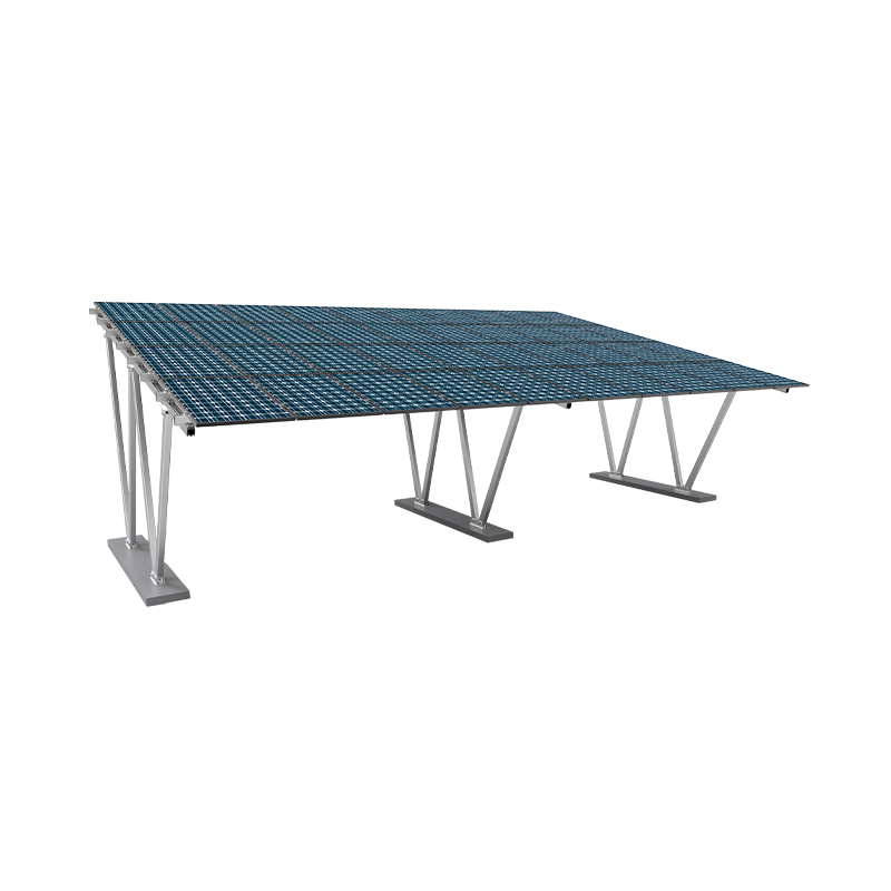
2026/07/02ソーラーカーポートインフラの即時価値 A カーポート PV マウント システム 車両を天候から保護しながら、十分に活用されていない駐車スペースを地域の発電所に変えます。向きの制約、構造上の荷重制限、近くの障害物による影に直面する可能性がある従来の屋上設置とは異なり、駐車場用太陽電池アレイは、高度に予測可能で最適化されたエネルギー収量を提供します。これらのシステムは、既存の舗装された敷地を活用することで、実用規模の地上設置に伴う土地取得のハードルを排除し、商業、産業、および組織のエネルギー移行にとって理想的な選択肢となります。 財務面と運用面の観点から、ソーラー カーポートを統合すると、次の 2 つの重要な目標が同時に達成されます。 グリッド依存のオーバーヘッドを削減し、二酸化炭素排出量を削減します。 操作スペースを犠牲にすることなく。商業用途では、適切に設計されたカーポート構造は、持続可能性への目に見える取り組みとして機能し、HVAC システムの構築、製造機械、EV 充電ネットワークなど、需要の高い局所的な負荷に直接対応します。 主な構造構成と材料 カーポート PV 取り付けシステムの構造的完全性は、その建築プロファイルと材料構成に大きく依存します。設計者は、美的要件と、高速風域や局所的な積雪制限などの厳しい機械的負荷変動とのバランスをとらなければなりません。 1. カンチレバー vs. マルチポスト基礎 カンチレバー構成では、太陽の天蓋を保持するために外側に伸びる単一支柱設計が採用されています。このレイアウトにより、地上レベルでの構造上の設置面積が最小限に抑えられます。 車両衝突のリスクを軽減する ドライバーの駐車操作を簡素化します。マルチポスト構成では、駐車区画の前部と後部の両方に柱を利用します。マルチポスト レイアウトにはより多くのスチールまたはアルミニウムのインフラストラクチャが必要ですが、車両の複数列をカバーする広いスパンのベイに優れた構造安定性を提供します。 2. 材料選択マトリックス 構造材料の選択は、取り付けシステムの寿命、メンテナンス スケジュール、および初期資本支出に直接影響します。構造用鋼と高強度アルミニウム合金は業界のベンチマークであり、それぞれが地理的および環境的ニーズに応じて異なります。 ソーラーカーポートフレームネットワークの構造材料の比較。 材料パラメータ 溶融亜鉛メッキ鋼板 陽極酸化アルミニウム合金 構造降伏強度 高 (10 メートルを超えるスパンに最適) 中程度 (6 メートル未満のスパンに最適) 耐食性 内陸環境に優れています 塩分濃度の高い沿岸地域に優れています 重量対強度比 重い(設置には重機が必要です) 軽量 (迅速な現場での手動組み立て) 相対コスト指数 ベースラインコスト標準 初期材料費が 15% ~ 25% 高くなります 工学的な考慮事項: 風、雪、基礎の深さ 建物の欄干の遮蔽効果の恩恵を受ける屋上の太陽電池アレイとは異なり、カーポートの PV 設置システムは、空力的な風による揚力に完全にさらされる開放構造の天蓋です。工学計算では、構造物の破損や壊滅的な隆起を防ぐために、局所的な風力学を考慮する必要があります。 機械的負荷の計算 エンジニアは、特定の地域の環境要因に耐えられるようにこれらのシステムを設計し、いくつかの重要な基準に対して構造の完全性をテストします。 風速耐量: 標準設計は通常、次の風荷重に対応します。 秒速60メートル 、特定の傾斜角を利用して全体の抗力係数を低減します。 積雪荷重係数: 北緯の構造物は、以上の強度をサポートするように計算されています。 2.0キロニュートン/平方メートル 積雪の影響が大きく、断面の厚さを強化した構造母屋が必要です。 傾きの最適化: 傾斜スケールを 5 ~ 15 度の間で調整することで、最適化された太陽放射照度の捕捉と、効率的な自然水の流出および瓦礫の除去のバランスが取れます。 基礎工学モデル 基礎は、ソーラーパネルの下向きの自重と風の上向きの力の両方に対してフレームワークを固定します。設置者は、土壌地質工学レポートに基づいて 2 つの主要な基礎スタイルを実装します。 場所打ちコンクリート橋脚: 深い円筒形の穴が駐車場の下地に直接ドリルで開けられ、鉄筋ケージで補強され、コンクリートで埋められます。これにより、 転倒の瞬間に対する最高の抵抗力 劣悪な土壌条件で。 プレキャストコンクリートバラスト: 主に、地下施設が深い掘削を妨げる場合に使用されます。あらかじめ製造された重いブロックは地表上または地表のわずか下に置かれ、アレイを固定するために質量重力変位に完全に依存しています。 水管理とインバータ統合アーキテクチャ 先進的なカーポート PV 取り付けシステムは、基本的な構造の安定性を超えて、運用上の使いやすさに対処する必要があります。車両と歩行者が毎日構造物の下を移動するため、冬季の駐車場の浸水や歩道の凍結を防ぐためには、雨水の流出を管理することが重要です。 水管理の革新 標準的な取り付けプロファイルにより、雨が個々の太陽電池モジュール間の隙間を通って自由に落ちることができます。ただし、商用グレードのカーポートには次の要件が必要です。 統合水管理システム 。最新のセットアップでは、パネルの継ぎ目の間にゴム製の EPDM ガスケットを使用し、局所的なアルミニウム製の内部雨樋と組み合わせています。流出水は、駐車スペースから構造垂木水路に系統的に誘導され、内部の垂直柱縦樋を下って、市の雨水管または周囲の貯留池に直接流入します。 システム電気バランス (BOS) 設計 電気ハードウェアの設置には、電圧降下を最小限に抑え、破壊行為や車両の偶発的な衝撃からコンポーネントを保護するための戦略的な計画が必要です。ストリングインバーターは、多くの場合、キャノピー構造デッキの真下の高い位置に取り付けられ、日陰になって手の届かない場所に保たれます。大容量の DC 配線は、密閉された金属配線路または構造母屋の空洞を確実に通過し、環境への暴露や機械的摩耗から配線を保護します。 財務パフォーマンスとスペース最適化の分析 カーポート PV マウント システムは、構造用鋼柱と基礎の要件により、標準的な地上マウントよりもワット当たりの初期資本投資が高くなりますが、組み合わせることで大きな収益をもたらします。 より高いエネルギー収量による二重用途土地の最適化 涼しい動作環境から。 両面フェイシャルのパフォーマンス乗数 カーポートは、両面受光型ソーラーモジュールの統合に非常に適しています。高いプロファイルにより、周囲の光が下のアスファルトまたはコンクリートの表面で反射し、パネルの背面に当たることができます。アルベド値の高いコンクリートの駐車面を利用すると、システムの総エネルギー出力を増加させることができます。 10%~15% 従来の単面パネルシステムと比較して。この追加のエネルギー出力は、システムの経済的回収期間を直接短縮します。 運用上の利点と相乗効果 カーポート設置の戦略的利点は、いくつかの主要な領域に広がります。 熱の軽減: 車両を遮光すると、夏のピーク時に車内の温度が最大 15 ℃下がり、車両始動時の局所的な空調負荷が最小限に抑えられます。 EV充電インフラの統合: 発電リソースを駐車場の真上に配置することで、レベル 2 および DC 急速充電ステーションの掘削コストが最小限に抑えられ、地域の電力網インフラが最適化されます。 除雪オーバーヘッドの削減: 屋根付き駐車ベイにより、冬季の運用サイクルにおける除雪と塩漬けに必要な人件費と設備費が大幅に削減されます。
2026/07/02


 中国江蘇省泰州市海陵区鳳凰東路60号文創ビル11階